A computer can list one physical accessory in several places. A dock, for example, may contain a hub, an audio interface and a network adapter. Device Manager offers different views of that arrangement, including a connection tree. This article shows how to compare those views and record what Windows reports. It also explains where the tree can be misleading: software relationships do not always match the cables you can see. Stay with viewing commands; disabling, removing or changing a device is outside this exercise.
Understanding Device Manager Architecture
Device Manager acts as a visual representation of the Hardware Abstraction Layer within Windows 11. It organizes hardware based on its specific function and communication protocol rather than purely physical presence. Understanding this hierarchy is essential for mapping connections effectively. Devices are grouped by class, which refers to a category of hardware that shares a similar function or communication method, such as Universal Serial Bus (USB) controllers, network adapters, or display adapters. The interface provides a structural overview that allows for the inspection of internal hardware communication paths.
Navigating Hardware Categories
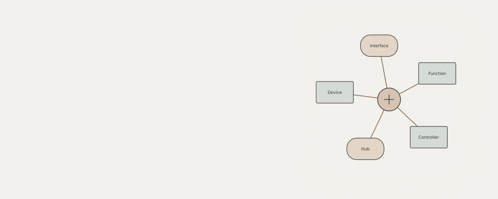
Windows 11 categorizes hardware to simplify the management of complex systems. When exploring these categories, users often encounter devices that serve as entry points for other peripherals. For instance, USB controllers are essential for managing data traffic between the processor and connected peripherals. A controller acts as a bridge, while a hub acts as a multi-port expansion device that increases connectivity capacity. Understanding these distinct roles helps in mapping how data flows from a specific peripheral through the system architecture.
The classification system also helps distinguish between internal motherboard components and external peripherals. Internal components are usually directly interfaced with the motherboard, whereas external peripherals utilize standardized connectors. Recognizing this distinction is vital during an audit, as it prevents the misidentification of a controller or port as a standalone device. By mastering the categorization, users gain the ability to logically group items based on their operational requirements and physical interface types, which is essential for troubleshooting or cataloging complex hardware setups without relying on external diagnostic software.
Procedure: Auditing Device Connections and Types
This procedure outlines the steps to perform a read-only inventory of device connections. It requires no modifications to the system and is strictly for observational purposes. Labels in the interface may vary based on your specific Windows 11 version or system manufacturer configurations.
By systematically expanding nodes in the Device Manager tree, you can trace the parent-child relationship of hardware connections. This relationship defines how a downstream device, such as a printer, relies on an upstream device, such as a USB controller, to function. Following this path allows you to accurately map the physical topology of your workstation environment.
- Launch the Start menu search bar and type 'Device Manager' to open the application window.
- Select the 'View' menu option in the upper toolbar and choose 'Devices by connection' to reorder the tree based on the system bus architecture.
- Locate the 'ACPI x64-based PC' node, which serves as the root for all connected system hardware.
- Expand the root node and subsequent branches to identify the PCI Express Root Complex and various USB Host Controllers.
- Identify a hub or controller node and click the expansion arrow to reveal the sub-devices currently associated with that specific connection point.
- Right-click a specific device in the list and select 'Properties' to open the device information dialog.
- Observe the 'General' tab to note the device status, which should indicate 'This device is working properly'.
- Navigate to the 'Details' tab and select 'Parent' from the 'Property' dropdown menu to see the identifier of the upstream device or hub the component is connected to.
- Verify the device type and manufacturer information provided in the properties window for accurate documentation of the hardware inventory.
- Close the properties window and return to the main tree to continue auditing other branches without making changes to the device state.
Interpreting System Status
When auditing device connections, interpretation of the status is paramount. A functional device typically reports that it is working properly. However, if an exclamation point appears, it signifies that Windows has recorded a problem. This does not necessarily mean a driver is missing or that a communication failure has occurred. It is important to note that no action in this tool is zero-risk and no action guarantees stability.
Boundary limitations within this tool include the inability to view devices that are physically disconnected unless they are retained as phantom nodes. Furthermore, the 'Devices by connection' view is the most accurate method for mapping physical data paths, whereas 'Devices by type' focuses on the classification of hardware functionality. Relying on the correct view ensures that your analysis of the hardware topology remains accurate and meaningful for the specific task of connection mapping.
To further refine your interpretation, consider the 'Events' tab, which records the history of device arrival and configuration changes. This chronological log can explain why a device might have stopped functioning or why it is currently showing a warning status. By combining the 'General' status with the 'Events' history, you can build a more complete narrative of the device's lifecycle within the operating system. This thorough investigation is key to maintaining a clear understanding of your hardware environment without resorting to unnecessary system interventions.
Role of Controllers and Hubs
Controllers function as the primary interface between the system bus and external peripherals. They manage the timing, electrical signal translation, and data arbitration required for communication. In Windows 11, these are typically identified under the 'Universal Serial Bus controllers' category. They are the essential gateway through which all USB traffic passes. Identifying these controllers is the first step in mapping any peripheral connection.
Hubs, by contrast, function as expansion points. A hub does not necessarily process data in the same capacity as a controller but serves to increase the number of available ports. When mapping devices, identifying the hub node allows you to determine how many devices are daisy-chained or clustered together under a single controller. This hierarchy is crucial for identifying bottlenecks or determining which physical port on a computer chassis corresponds to a specific logical device entry.
By observing these hubs in the 'Devices by connection' view, users can effectively isolate specific hardware issues to either the hub itself or the device connected to it. For instance, if several devices connected to the same hub stop responding, the issue likely resides with the hub's connection to the upstream controller or the hub hardware itself. This analytical method allows for logical deduction and precise inventory management, ensuring all devices are correctly accounted for within the broader structure of the system.
Analyzing Composite Device Structures
Composite devices present a unique challenge in device mapping. Because they register as multiple logical entities, they can appear fragmented across the Device Manager tree. For example, a specialized desktop docking station often includes network adapters, audio components, and video interfaces. These are grouped into their respective classes for Windows to manage them efficiently.
To effectively map a composite device, one must identify the shared parent node. By using the 'Devices by connection' view, you can identify that multiple disparate items share a common upstream controller. This confirms that these items, despite appearing in different categories, are part of the same physical hardware assembly. This method is the standard way to maintain a clean inventory of hardware without attempting to disable or remove devices.
This structural analysis is particularly beneficial when managing high-end peripherals that feature complex internal electronics. By tracing each function back to a single shared hub or root controller, you gain a deep understanding of the device's internal architecture. This provides a clear, documented record of how your system components relate to one another, preventing the common mistake of assuming that separate logical entries represent distinct physical pieces of hardware.
Boundaries and Best Practices for Inventory
When performing an inventory, it is vital to adhere to read-only practices. Modifying device states, such as disabling a component, can have unintended side effects on system stability, especially if the device is a bus controller. Always maintain a clear distinction between internal motherboard components and external peripherals. Internal components are usually soldered or directly interfaced with the motherboard, while external peripherals use standard connectors.
The 'Details' tab provides the most granular information for mapping. Properties like 'Bus reported device description' or 'Hardware IDs' provide technical identifiers that can be matched against manufacturer data sheets. Avoid changing settings in the 'Driver' tab, as this is outside the scope of inventory mapping. By focusing solely on observation, you ensure that the system configuration remains in its current state while you document the existing topology.
As a best practice, record the Parent-Child relationships observed in the 'Devices by connection' view systematically. Documenting the specific controller associated with each peripheral node provides a robust map for future reference. This meticulous approach ensures that even if devices are moved or reconfigured, you have an accurate baseline of the original hardware setup, allowing for efficient comparisons over time.
Worked Example: Mapping a Multi-Function Peripheral
Consider a scenario where a user connects a multi-function keyboard with an integrated USB hub and audio output. When viewed in Device Manager by connection, the user might see a root USB controller branch. Expanding this reveals an 'Enhanced Host Controller' which leads to a 'Generic USB Hub'. Under this hub, the system reports a 'USB Input Device' (the keyboard), a 'USB Audio Device', and an 'Internal Hub'.
This mapping confirms that the audio and keyboard functions are actually routing their signal through the hub integrated into the keyboard chassis itself. By noting this path, the user accurately identifies that these three items are physically part of one device. This type of analysis avoids the error of treating the keyboard and the audio output as two separate, disconnected peripherals, ensuring that the hardware map reflects the physical reality of the desktop environment.
In this example, the 'Details' tab could be used to verify the shared manufacturer IDs across all three entries, further confirming they belong to the same assembly. By following this method, the user creates a reliable, high-fidelity map of the hardware, ensuring that the documentation precisely matches the physical hardware layout without modifying any settings.
Computer & System
Note these before you change anything
Useful facts to have to hand while reading about mapping device connections.
- Motherboard or computer model and firmware version
- Chipset driver package version
- Any firmware settings changed from defaults
- Unknown devices listed in Device Manager
Computer & System: One selected path: a device on a chipset bus
- Operating systemmanages devices
- Chipset driversidentify buses and power features
- ChipsetPCIe, USB and SATA links
- Firmware (UEFI)initialises hardware at start-up
- Attached deviceson those links
Frequently asked questions
How is the connection view different from the type view?
The type view groups devices by category, such as audio or network adapters. The connection view organizes entries by their reported relationships. A device may be easier to locate in one view than the other, so compare them rather than expecting identical lists or arrangements.
Does a hub entry correspond to a box on my desk?
Not always. A hub can be inside a computer, display, dock or other accessory. The tree reports a connection relationship, not the enclosure’s appearance. A single visible cable can lead to several functions or devices, depending on the product’s internal design.
Can one accessory have several device instance IDs?
Yes. Different functions or devices inside one accessory can have separate entries and identifiers. A shared enclosure does not require a shared instance ID. Use the reported connection relationships and manufacturer documentation together; similar names alone do not establish that entries belong to the same physical object.