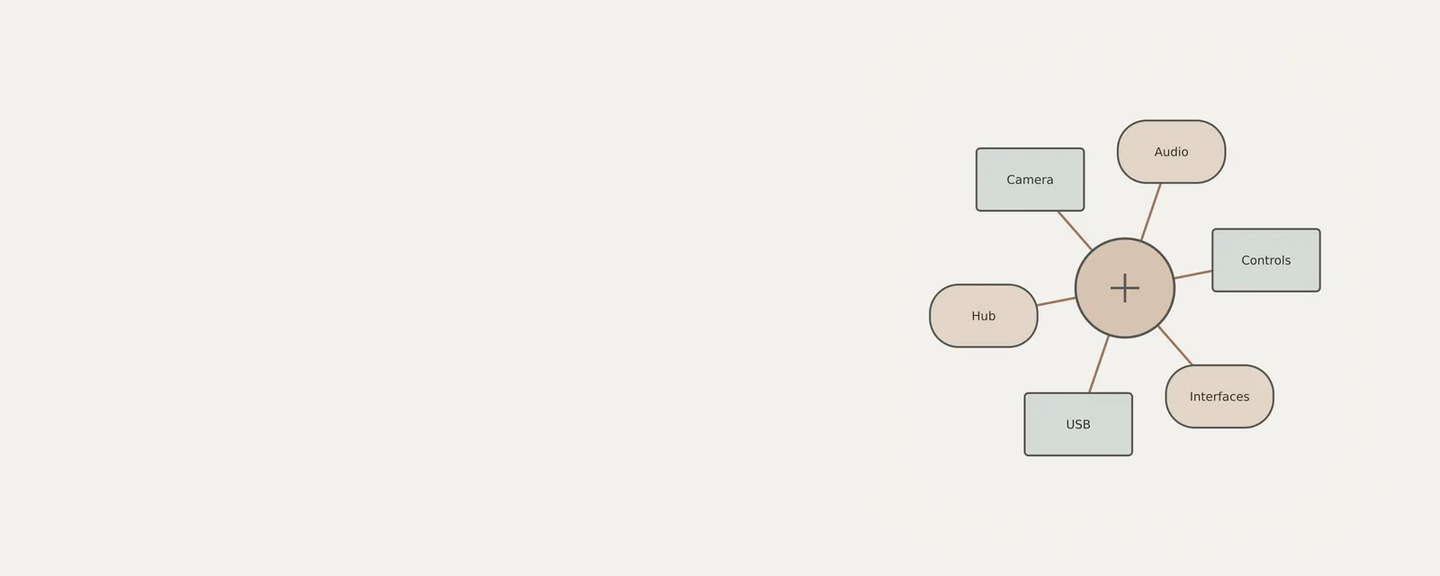
One USB accessory can expose several functions, such as a camera, microphone and set of buttons. Windows may therefore show multiple entries even though only one physical item is connected. This article explains how to inspect those entries and compare them with a hub-based arrangement. The connection tree is useful evidence, but it does not always reveal the complete internal design of an accessory. Each function can have its own device instance identifier. Observe the reported relationships without disabling interfaces or changing device settings to simplify the list.
Conceptualizing USB Composite Architecture
A USB composite device operates by identifying itself to the host computer as an entity possessing multiple interfaces. Each interface represents an individual capability of the device. For example, a high-definition webcam might appear as a video stream interface, an integrated microphone audio interface, and a secondary HID interface for physical capture buttons. These logical interfaces exist independently within the system, even though they share a single physical USB connection to the motherboard or an external hub.
Substantively, the composite architecture shifts the complexity from the hardware wiring to the firmware layer. In earlier bus standards, adding functionality often required additional physical cables or separate controller hardware. With USB, the composite class allows manufacturers to bundle diverse services into one controller. When the operating system initializes the connection, it queries the device descriptor to determine how many 'interfaces' or 'logical endpoints' exist. If a device has three functions, it effectively tells the operating system to load three separate drivers or functional modules, all reporting back to the same physical hardware address.
Initiating Read-Only Hardware Inventory
Before beginning the inspection, note that Device Manager is not a read-only tool. While the goal is to view the organization of hardware, be aware that modification of system settings or drivers can occur. No action is zero-risk or guarantees stability. To access the inventory interface, use the following procedure, noting that interface labels and organizational groupings may appear slightly different depending on your specific hardware configuration and system version.
The inventory process utilizes the standard Windows system management tools to categorize hardware connections by their connection type and functional capability. By observing the tree structure in the system dialog, users can isolate specific hardware nodes for investigation. This systematic approach allows for a granular view of device enumeration, identifying whether a peripheral is performing as a single functional block or a composite assembly.
- Open the Windows 11 search bar, type 'Device Manager' without quotes, and select the corresponding utility from the results list.
- In the primary window, locate the 'View' menu in the top navigation bar to confirm that your current view is set to 'Devices by type' for an initial logical breakdown, or 'Devices by connection' for a physical topology view.
- Expand the 'Cameras,' 'Sound, video and game controllers,' or 'Human Interface Devices' categories to see individual functions associated with the hardware.
- Right-click on an entry that matches your peripheral to open its context menu, selecting 'Properties' to view the specific hardware identifiers provided by the device.
- Select the 'Details' tab within the Properties dialog, then navigate the 'Property' dropdown menu to choose 'Parent' or 'Service' to see how the system associates these interfaces with the overarching device node.
- Observe the hierarchy in the tree display, noting which interfaces appear indented under a parent device entry, which signifies the composite relationship between the physical unit and its logical functions.
- Review the 'Events' tab to see timestamped entries regarding the enumeration of these interfaces, confirming that the system recognizes each part of the composite unit during the connection cycle.
- Conclude the session by closing the dialog windows, leaving the underlying configuration unchanged from its initial state.
Interpreting Connection Hierarchies
When viewing devices by connection, the tree structure reveals the underlying physical path. A hub is a hardware component that expands the number of available ports, and devices connected to these hubs appear as branches on the tree. In a composite setup, you will observe the parent device listed as a single entry that encompasses several 'child' nodes or sub-nodes. These children represent the distinct functions that the system has enumerated. If you see multiple interfaces under one hardware identifier, you are looking at the logical breakdown of a single physical device.
By comparing the 'Devices by type' view against 'Devices by connection,' users can troubleshoot where a device is physically located in relation to the main system board. For instance, if a device is connected via a multi-stage daisy-chained hub, the latency and power management characteristics will differ significantly from a device connected directly to a root hub integrated onto the motherboard. This hierarchy provides visual evidence of the physical bus depth.
Analyzing Hardware Properties and Metadata
The 'Properties' dialog acts as the source of truth regarding the hardware's internal identification. Within the 'Details' tab, the 'Device instance path' is a critical field. This string provides a unique identifier for the hardware, which often contains the Vendor ID (VID) and Product ID (PID). For a composite device, these IDs are typically identical across the various logical interfaces, indicating they belong to the same physical unit.
Additional fields like 'Parent' provide a link to the USB controller or root hub responsible for the connection. By tracing the 'Parent' value, a user can confirm that each component of the composite device maps back to the same physical USB port on the motherboard. This confirms that the internal organization is consistent with the physical deployment of the hardware. To illustrate, if you have a headset with a microphone and a speaker component, you will find both share a common parent hardware instance string, proving they occupy a shared logical descriptor space.
Analyzing these strings is a standard way to verify identity without external tools. The hardware ID string is typically formatted as 'USB\VID_xxxx&PID_xxxx'. When you see the same VID and PID repeating across multiple entries in the Device Manager hierarchy, it indicates that these are indeed sub-functions of the same composite controller, as opposed to different devices manufactured by the same vendor but plugged into different ports.
Boundaries of System Visibility
It is important to recognize that Windows 11 provides a view based on the information the hardware itself reports to the kernel. It is important to recognize that 'Show hidden devices' does not reveal every possible device or background process.
However, even with hidden devices visible, there are inherent limitations. The system displays what is requested by the device firmware. If a hardware manufacturer chooses to bundle certain functions in a way that the operating system perceives as a single, opaque entity, those details will remain hidden. Users should rely only on the explicitly provided fields in the Properties dialog to ensure they are interpreting accurate system-reported data rather than making assumptions about the device's inner workings.
Consider the case of a modern interface device with integrated encryption or secure memory storage; these internal security modules are often abstracted away from the operating system to prevent tampering. In such cases, Device Manager only shows the interface the OS needs to interact with, such as a mass storage class identifier, while the security controller remains entirely invisible to standard system-level inventory. Understanding these boundaries prevents misinterpretation of the device's capabilities when checking for system-level anomalies.
Worked Examples of Logical Grouping
Consider a scenario involving a docking station. A docking station is a classic example of a composite device that provides networking (Ethernet), display (HDMI/DisplayPort), and data (USB-A/C ports) through a single connection. When viewing this in Device Manager, the parent node will likely be listed under 'Universal Serial Bus controllers' as a 'USB Composite Device.'
Expanding this parent node reveals multiple functional branches: 'Network adapters,' 'Display adapters,' and 'Human Interface Devices.' Each branch represents a logical function that operates independently but relies on the primary USB connection. If you check the 'Details' tab for the display adapter function and compare the 'Parent' property to the network adapter's 'Parent' property, you will find they match. This confirms that all these features are routed through the same physical connection point to the computer.
Another practical example is a high-end gaming keyboard with integrated RGB lighting control and a physical USB pass-through port. In the device tree, the keyboard controller might report as a composite device with two HID keyboard inputs (one for standard keys, one for media macros) and a USB hub function to power the pass-through port. By inspecting the hierarchy, you can trace these distinct services back to the keyboard’s internal controller, distinguishing them from a separate keyboard and mouse combo connected to the same hub.
Maintaining System Integrity
This observational approach reinforces the importance of monitoring. While utilizing only the information panels provided is safe, be aware that Device Manager has state-changing controls. No action is zero-risk or guarantees stability. Any interaction with the device properties should be strictly limited to reading the provided metadata. If a device requires specific software to configure its internal settings, that software should be managed independently of the system's core device management utility.
System administrators and power users frequently use this method to audit peripheral health and ensure that devices are properly enumerated. By observing the connection hierarchy, one can verify that USB devices are receiving sufficient power and that the data bus is properly identifying all logical functions. This transparency is the cornerstone of effective hardware inventory in a Windows-based architecture. Consistent monitoring through this methodology prevents accidental system instability that could arise from modifying sensitive driver parameters or configuration files.
Ultimately, the goal of auditing the device tree is to maintain a clear map of what is connected and how it consumes system resources. By understanding the parent-child relationships within the USB architecture, one gains a robust mental model of how Windows 11 manages external hardware. This knowledge empowers users to distinguish between legitimate composite functions and potential connectivity issues, ensuring that each logical unit is correctly identified and functioning as expected within the broader hardware ecosystem.
USB & Peripherals
Note these before you change anything
Useful facts to have to hand while reading about identifying composite peripherals.
- Which port the device was in, and whether a hub is involved
- The device's name and status in Device Manager
- Power management settings on USB root hubs
- Any companion software the device relies on
USB & Peripherals: Input from a device (output devices run the other way)
- Devicekeyboard, mouse or pad
- Port or hubphysical connection
- Host controllermanages the bus
- Class driverfor example HID
- Applicationreceives the input
Frequently asked questions
Can one USB accessory expose several functions?
Yes. A composite device can expose functions such as audio, video and input controls through one physical connection. Windows may create separate entries for those functions. Their appearance is not, by itself, evidence that unexpected hardware has been added or that an entry should be removed.
Can I simplify the list by disabling extra functions?
That is outside this inspection exercise and can remove capabilities the accessory uses. A longer list can be normal for multifunction equipment. Read the properties and connection relationships instead of changing device states merely to make the tree look closer to the number of objects on your desk.