What this section covers
A request can pass through several software components before a device performs an operation. Function, bus and filter roles help describe those relationships, but a real driver stack is not always one simple chain. Composite devices can expose several functions while sharing a physical connection. This guide explains the roles and a limited connection-view exercise, keeping topology separate from diagnosis. A parent-child view is useful context; it is not a complete stack trace or proof that every request followed the intended route.
Tracing Request Flow Through System Interfaces
A hardware request begins as an application-level command directed toward a specific functional interface. The operating system intercepting this command must determine which bus architecture handles the communication, such as USB or PCIe. This decision process relies on the device stack to route data correctly, ensuring that the request is packaged into a format the hardware can process efficiently.
Observing the path reveals that requests often pass through various filters before reaching the primary controller. These filters monitor or modify traffic for specific management tasks, like power consumption or data integrity verification. When a request is stalled, it is often due to a filter misinterpreting the command or a conflict in the bus protocol expected by the target device.
- Open the hardware management console to view device connections.
- Locate the specific target peripheral within the tree structure.
- Select the properties menu to observe the functional hierarchy.
- Review the resource tab to identify allocated bus address ranges.
- Inspect the status field to confirm the current active state of the interface.
Managing Composite Device Functions
Composite devices present unique challenges because they encapsulate multiple distinct functions under a single physical connection. A single USB device, for instance, might appear as a keyboard, a mouse, and an audio controller simultaneously. Composite functions can have distinct logical interfaces while sharing physical links; they need not have independent dedicated physical channels.
Managing these devices involves monitoring how the bus partitions the available bandwidth among the various functions. If one function reports an error, it does not necessarily mean the entire device is unresponsive. By isolating the individual functional nodes in the management console, you can determine if a specific sub-component is failing while others continue to operate normally.
- Expand the node representing the composite device in the management interface.
- Identify the individual sub-components listed as separate functional nodes.
- Review the hardware ID for each specific sub-function to verify its purpose.
- Check the operational status of each individual sub-component separately.
- Verify if communication errors are isolated to one function or impacting the entire bus.
Interpreting Bus and Filter Relationships
The relationship between the host controller and the device depends heavily on the bus protocol. Filters act as intermediaries that can inject signals or prevent certain commands from reaching the hardware. Understanding these relationships is critical when troubleshooting unexpected behavior, as a filter might be performing silent rejections of requests that the main controller would otherwise accept.
During standard operations, these filters are transparent, but they can become bottlenecks if they are misaligned with the hardware requirements. When evaluating a connection, checking the filter list associated with a device can reveal if third-party modules are interfering with the expected communication flow. This inspection does not change the physical connection but clarifies why data might be failing to arrive at the endpoint.
- Navigate to the detailed device properties window for the relevant hardware.
- Switch to the driver details view to see the stack of loaded filters.
- Examine the list of filter modules to identify non-standard entries.
- Compare the current filter stack against known base-level configurations.
- Log the presence of additional filtering software that might alter incoming data streams.
Analyzing Local Connection Views
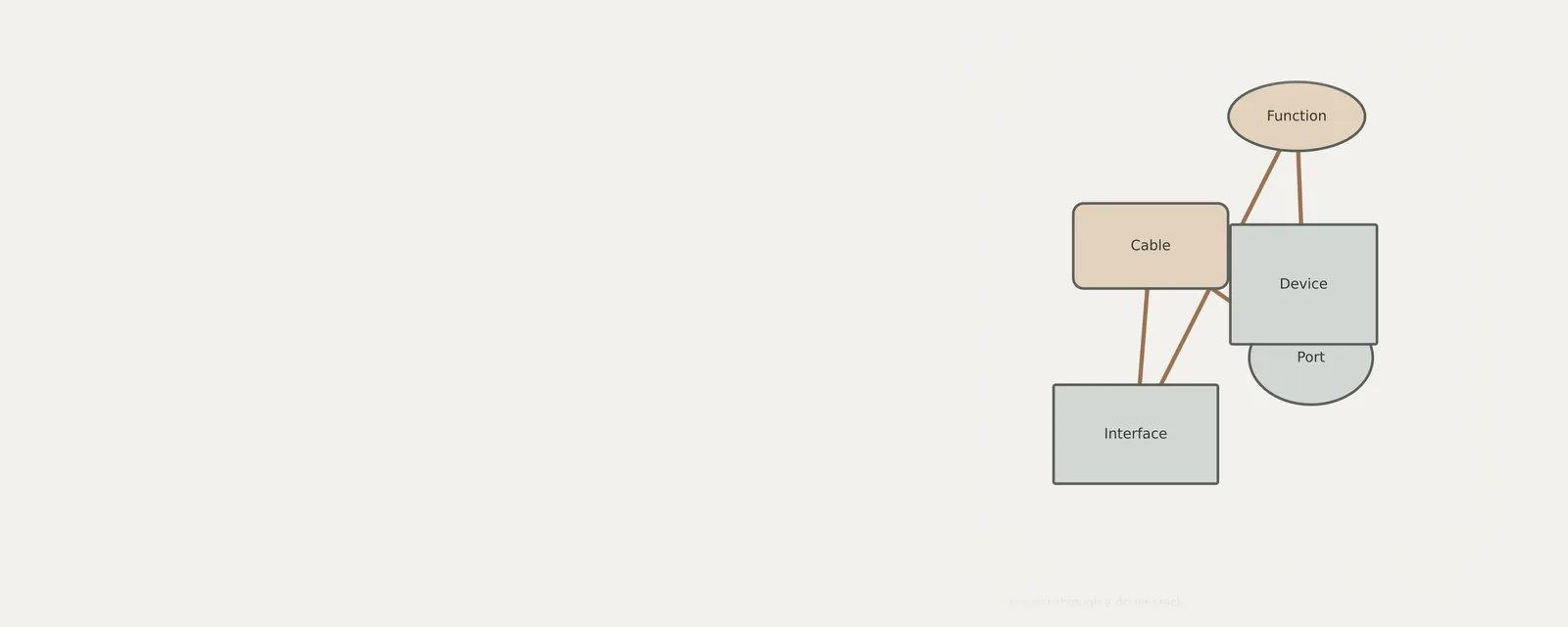
Local inspection views provide a snapshot of the current connection state without the need for exhaustive stack tracing. These views highlight the physical connection point and the associated bus link, allowing for a quick assessment of physical integrity. If the connection view shows a broken link or a missing parent controller, the issue likely resides at the physical or bus level rather than the software stack.
These views are useful for verifying that the device is detected correctly as a child of the intended root hub. A connection view helps describe the hierarchy reported by the system; it is not a full driver-stack trace or proof that a request followed the intended route. If the device appears detached or improperly parented, physical reconfiguration is often the first step to restoring reliable communication.
- View the device in the tree structure organized by connection point.
- Select the parent node to ensure the root controller is functioning properly.
- Assess if the peripheral is correctly enumerated under the expected bus host.
- Confirm that no alerts are flagging the connection as invalid or degraded.
- Cross-reference the port number shown in the view with physical hardware labeling.
Recognizing Limitations in Stack Tracing
Relying on software-based inspections has inherent limits when diagnosing hardware failures. While you can see the interface commands, these tools cannot display the raw electrical signals or the internal logic states within the hardware itself. Misinterpreting this gap often leads to unnecessary attempts at software reconfiguration when the true issue is a hardware component failing at the firmware or electrical layer.
Focusing on the software stack allows for the correction of interface errors, but it is not a complete diagnostic solution. When software indicators suggest a connection is active despite persistent communication errors, the failure may be occurring at a hardware level that the OS layer cannot monitor. Recognizing these boundaries prevents wasted effort and directs attention toward external hardware factors like faulty cables or power instability.
- Evaluate the success of software-side interface communication.
- Distinguish between errors reported by the OS and physical device malfunctions.
- Check external indicators like LED status or external power supplies.
- Consider if the failure persists when moving the device to a different host port.
- Review whether recent hardware additions are consuming excessive bus power resources.
USB & Peripherals
Note these before you change anything
Useful facts to have to hand while reading about following a request through a driver stack.
- Which port the device was in, and whether a hub is involved
- The device's name and status in Device Manager
- Power management settings on USB root hubs
- Any companion software the device relies on
USB & Peripherals: Input from a device (output devices run the other way)
- Devicekeyboard, mouse or pad
- Port or hubphysical connection
- Host controllermanages the bus
- Class driverfor example HID
- Applicationreceives the input
Frequently asked questions
Why does a single device appear as multiple entries in the manager?
A single physical device often provides multiple functional interfaces to the operating system. These separate entries allow the system to treat each function, such as audio and data input on a headset, as a unique entity, ensuring that each capability receives the appropriate software resources and management.
Can software changes resolve all connection failures?
Software management can resolve failures caused by misconfigured drivers or conflicting interface filters. However, if the root cause is a physical break, electrical interference, or hardware component failure, software adjustments will not be effective. In such cases, the issue must be resolved by addressing the physical hardware connection.
What is the purpose of a filter in a device stack?
Filters reside in the stack to monitor, analyze, or modify requests passing between the host and the device. They are frequently used for adding custom functionality, such as enhanced power management or data encryption, but they can sometimes interfere with standard communications if they are incorrectly configured or incompatible.
Is checking the device hierarchy sufficient for troubleshooting?
The hierarchy provides a clear view of how hardware is connected to the bus, which helps in identifying connection errors or missing parent drivers. While it is a highly effective way to confirm logical connectivity, it cannot replace physical inspection when the problem stems from damaged cables or faulty hardware ports.